Monigear Email Notification Setup Guide
Monigear network device email notification HOWTO
This document uses Monigear NTHM (Network temperature and humidity monitor) to send emails as an example to demonstrate how to set up the email notification function of Monigear series network monitoring devices, and introduces the relevant concepts of alarm events at Monigear device monitoring points.Example of a email notification
Traditional SMTP email sending
In recent years, due to security concerns, major email service providers have shifted to more secure authentication methods. However, many enterprises still use traditional SMTP email as their internal email service. This chapter explains how to set up this method.
In order to show how to use this method to send email with a monigear device, I registered an account, zhongwenqing68@163.com, on Netease's 163.com email website. For security reasons, the email account does not enable POP/SMTP by default. This function needs to be enabled in the system settings on the webpage. When enabling SMTP, a unique password will be displayed. This password is only displayed once and must be saved. This password is the SMTP password for this account.
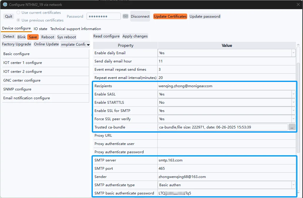
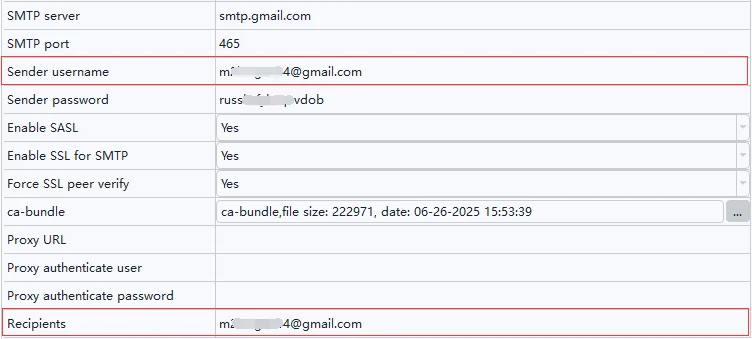
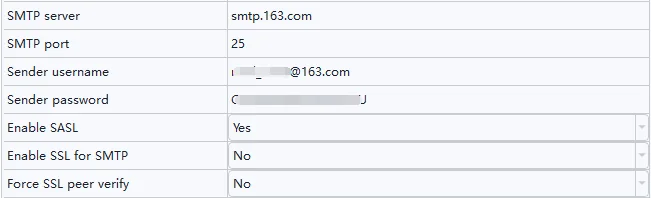
The settings directly related to sending a traditional SMTL emails are those shown in the two blue boxes in the image above, explained below:
Recipients is the email address to receive emails.
Enable SSL: Generally, select Yes.
Enable STARTTLS: This depends on the email server. 163.com doesn't require this, so select No.
Enable SSL for SMTP: Because 163.com's mail server requires this, you must select Yes.
Force SSL peer verify: This is the option for two-way authentication of digital certificates. Selecting Yes provides higher security.
Trusted ca-bundle is a root certificate bundle provided by your trusted organization, here using the Mozilla CA certificate store, you can download through this link. Alternatively, you can use the cabundle file in Linux.
SMTP Server is entered based on your server's IP address or domain name.
SMTP Port is also entered based on your email server's configuration. Here, 465 is used as the SSL port, so the SSL-related settings above must be configured correctly; otherwise, errors will occur when establishing an SSL connection with the email server. If your email server uses port 25, it is an unencrypted port, and "Enable SSL for SMTP" should be set to "No". These settings must be correct for a connection to be established.
“Sender” corresponds to the SMTP username, which is my email address in this case.
SMTP Authenticate Type: For traditional SMTP methods, this must select "Basic authen".
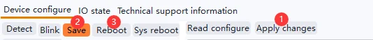
After the settings are completed, click Apply Changes -> Save -> Reboot to take effect.
After rebooting, go back to the Email configuration category in the configuration tool, and then to "Email Test". Click to perform an email test. As long as the settings are correct, you should be able to send emails successfully.
Preparations for sending Gmail emails via traditional SMTP
The following example uses Gmail to send emails via the standard SMTP protocol. It should be noted that many ordinary mail servers are simpler than Gmail, allowing login directly with a username and password. The setup for these is relatively simple, and you can start from Chapter 3.
By default, Gmail enables the SMTP function (other types of mailboxes may need to manually enable the SMTP function, you can search for relevant tutorials online), and you need to add an App password for the SMTP function.
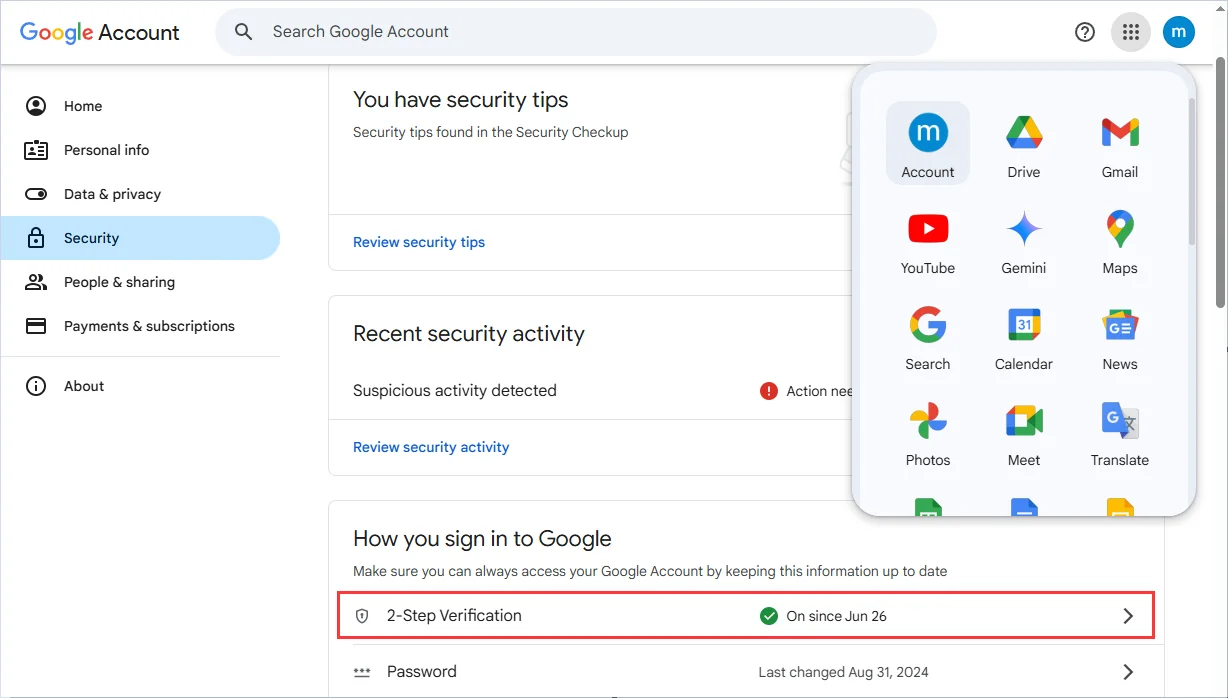
Click on Google apps, select Account, and click Security to enable two-step verification
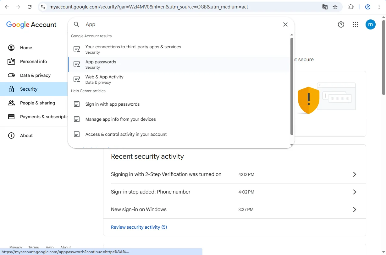
2)After enabling 2-Step Verification, enter App in the search box above and select App passwords
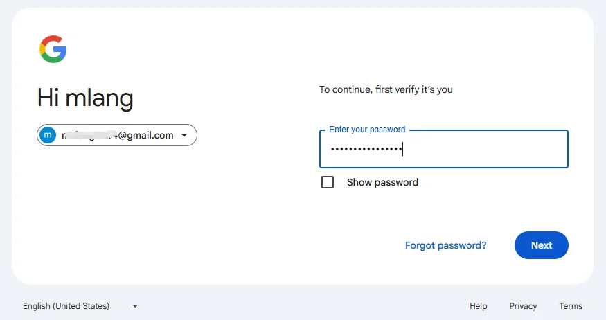
3)Enter your login password to confirm your identity
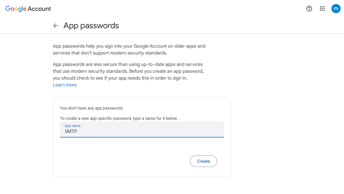
4)Enter the name of the application, e.g. SMTP (the name can be customized), and click Create
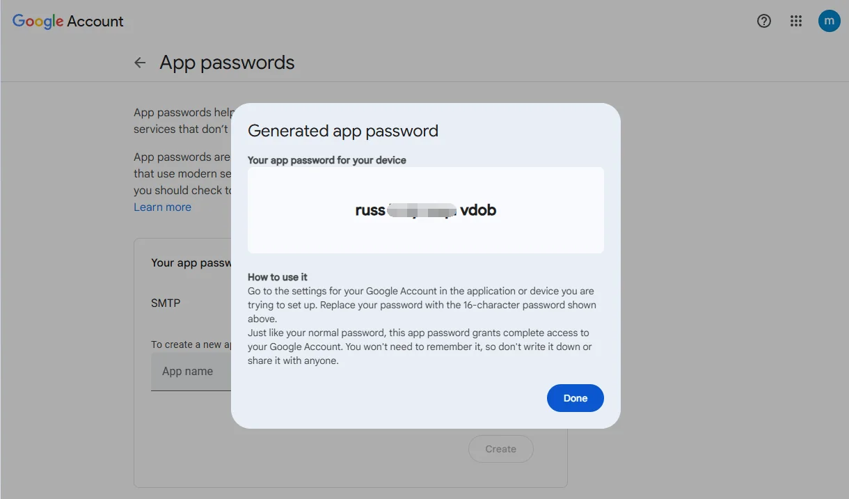
5)Copy the password down for later configuration
Note: After this page is closed, you cannot get the password again, you can only delete and recreate it.
Preparations for sending emails with OAUTH2
The traditional "username + password" method has been disabled by Microsoft since 2022, and Google may also disable it. XOAuth2 will replace the basic authenticate method, XOAuth2 is an extension of OAuth 2.0 to the email protocol. Its core process is: the device obtains a refresh_token through authorization, then uses it to repeatedly exchange for temporary access_tokens, and finally sends emails via SMTP. This method eliminates the need to store user passwords on the device, offering high security and making it suitable for embedded devices.
Because our device has limited display capabilities, we need to complete the one-time authorization in a PC environment with a browser to obtain the refresh_token, and then write it to the device configuration file. Therefore, a preparation process is required.
Preparation process for Gmail OAuth2
Preparation: A Gmail email address (a dedicated sending email address, not your main personal email address, is recommended) with IMAP access enabled.
https://mail.google.com/mail/u/0/#settings/fwdandpop
Create a project in the Google Cloud Console. Access https://console.cloud.google.com, and finally, log in to your personal account using Chrome to open the webpage above. The result should look like this:
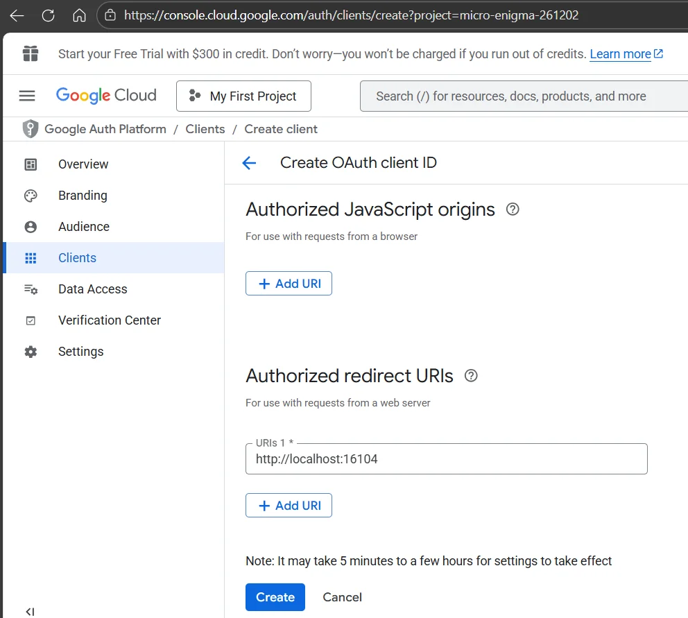
The "Authorized redirect URIs" here should ideally be filled with http://localhost:16104 as shown in the image above, because it needs to match the token utility in our devcfg.exe tool later.
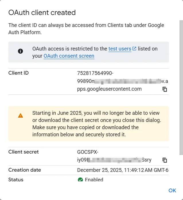
After clicking "Create," the following interface will appear. You must record the Client ID and Client secret. Once this dialogue is closed, the client secret will no longer be displayed; you will have to recreate it.
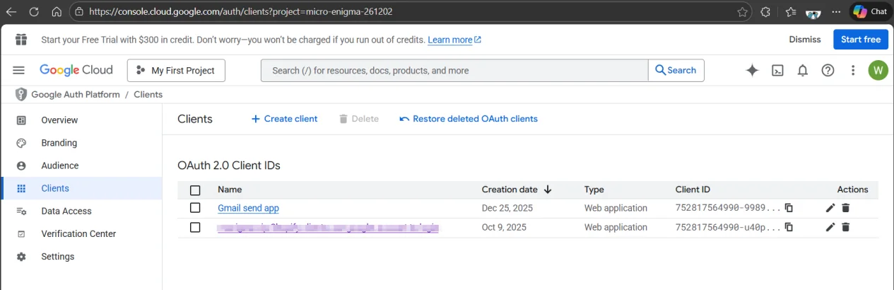
The list of Google Cloud clients looks like the screenshot below.
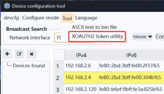
Next, use our device configuration tool software. Go to the main menu and select "tool" -> "XOAUTH2 token utilities".
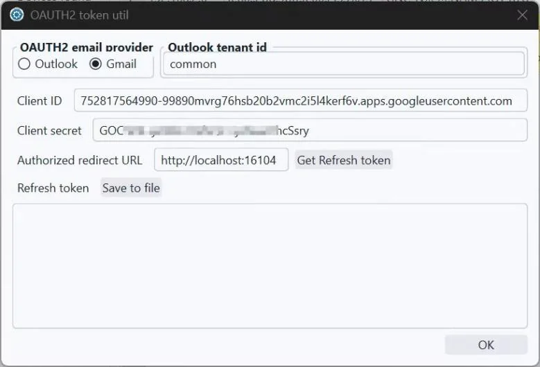
After entering your Client ID and secret, ensure the "Authorized redirect URL" matches your Google settings. Clicking "Get Refresh token" will bring up your default browser, prompting you to select your Google account. You'll then see a message indicating the application isn't verified by Google; simply select "Continue." Once authentication is complete, you'll see the refresh token below. You can copy it or save it as a file, but be careful to save it securely.
There's a possibility your browser might wait indefinitely without returning, especially when using a VPN.
Preparation process for Outlook OAuth2
To send emails via XOAUTH2 using an Outlook account (such as xxx@outlook.com, xxx@hotmail.com, or a Microsoft 365 work/school account), the following key steps are required. This process is similar to Gmail, but differs in Azure AD app registration and required permissions.
Prerequisites:
A Microsoft account (personal or organizational).
IMAP/SMTP access must be enabled (enabled by default for most accounts).
You must have permission to register applications in Azure AD (personal accounts can do this; enterprise accounts may require administrator approval).
Step 1: Register your application in the Azure portal
Access: https://portal.azure.com/#blade/Microsoft_AAD_RegisteredApps/ApplicationsListBlade
Sign in to the Azure portal using your sender email account. Navigate to Navigate to Azure Active Directory > App registrations > New registration.
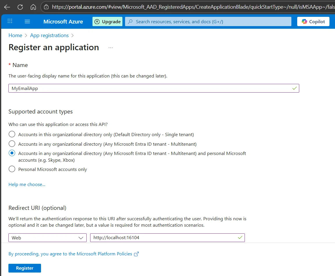
Enter a name: For example, MyEmailApp
Supported account types: Select "Accounts in any organizational directory and personal Microsoft accounts"
Redirect URI: Select "Web", then enter http://localhost:16104 (used to generate a token; not actually used in SMTP, but requires the same settings when obtaining a token using our configuration tool).
Click "Register". Obtain the Client ID (Application ID): On the "Overview" page, copy the "Application (Client) ID" → This is your client ID.
Create a Client Key:
1. Go to "Certificates & Keys" → "Client Keys" → "New Client Key".
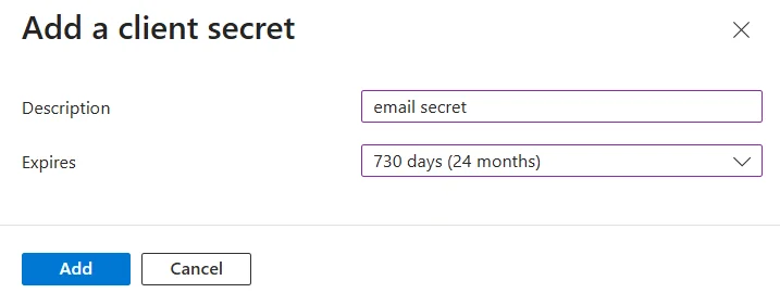
2. Add a description (e.g., SMTP key) and set an expiration time (e.g., 24 months).
3. Click "Add," and then immediately copy the generated key value (shown only once!) → This is your client key; save it now, as it won't be displayed again.
Step 2: Configure API Permissions (Critical!)
Go to API permissions → Add a permission.
Select Microsoft Graph → Delegated permissions.
Search and check exactly these permissions:
SMTP.Send(Note: NOT Mail.Send — that’s for Microsoft Graph API, not SMTP!)
offline_access (required for refresh tokens)
Click Update permissions.
Important: Click “Grant admin consent for [your tenant]” and confirm. (For personal accounts, click “Grant consent for …”)
After grant admin consent, it will be looked like below
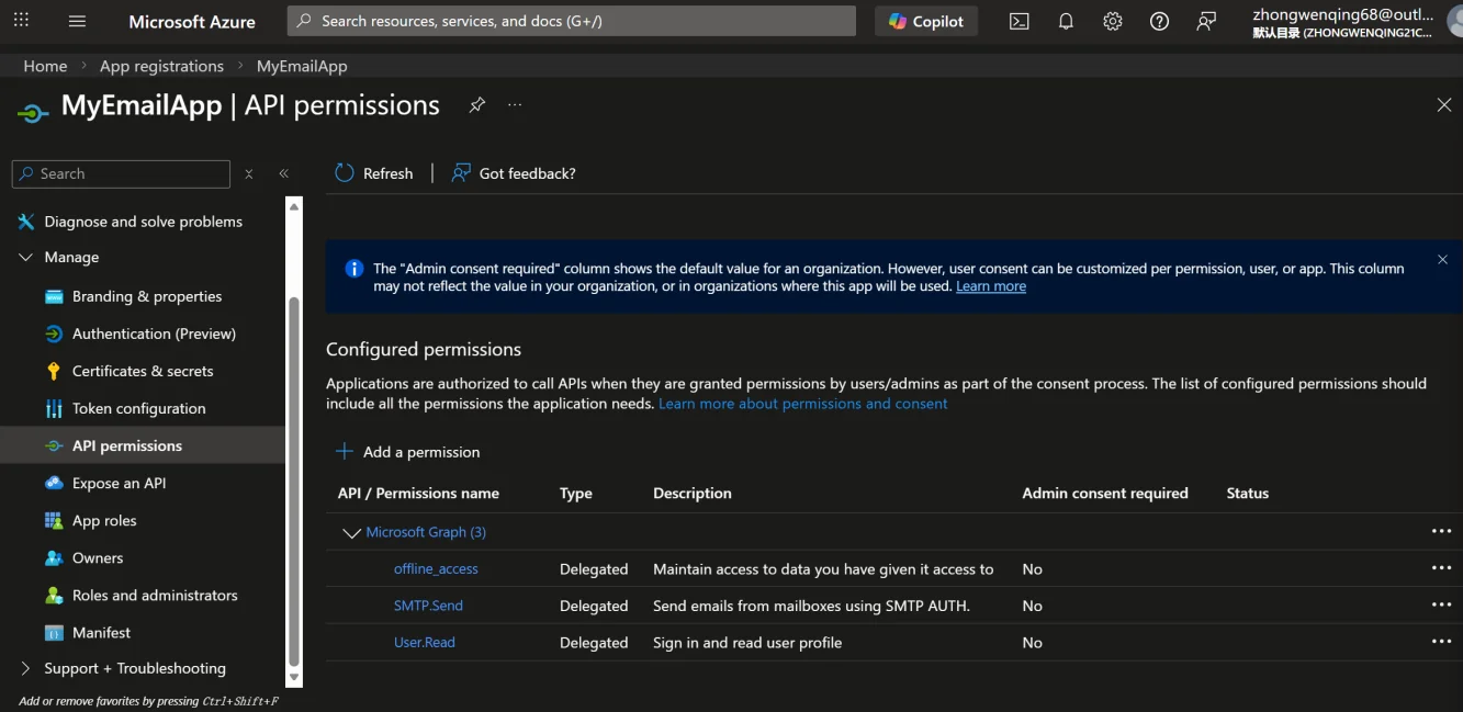
If you do not see SMTP.Send, your account type may not support using SMTP via OAuth2 (common in older or restricted enterprise accounts).
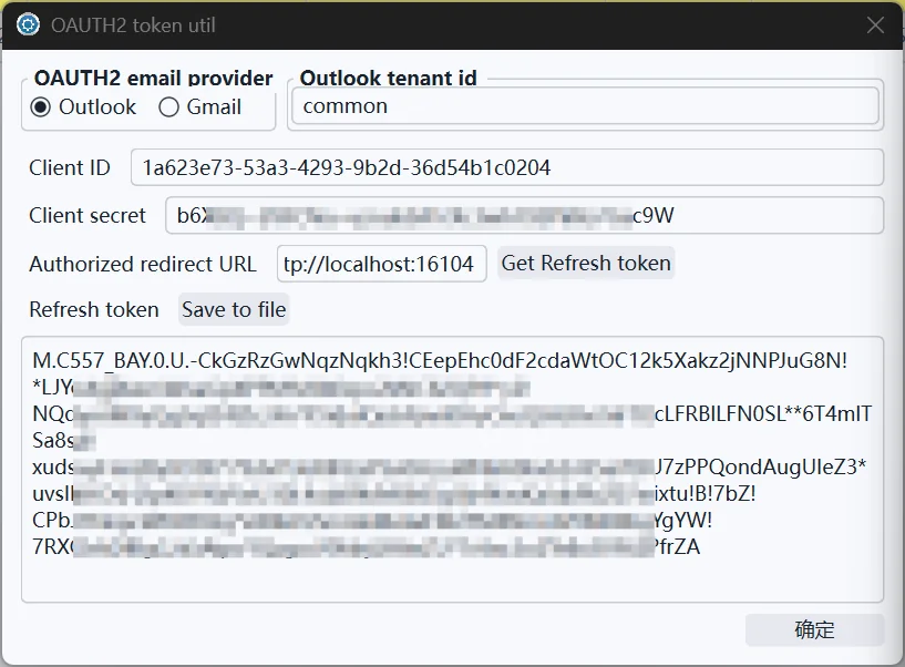
Next, use our configuration tool software by going to tool->"XOAuth2 token utilities" in the main menu.
Enter your Application ID in the Client ID field. Important notes: Use the default "common" for the tenant ID. After entering the recorded Client secret, ensure that the "Authorized redirect URL" matches the settings in Azure. Clicking "Get Refresh token" will open your default browser. Select "Agree" to authorize successfully. The obtained token will be displayed in the Refresh token section below. Outlook's token is relatively long, so choose to save it to a file. Ensure this file is secure and not leaked. The result is shown in the image below. The preparation is now complete, and you have obtained the files and data needed for device email settings.
Configure email notifications for the device
Basic SMTP Authentication Configuration
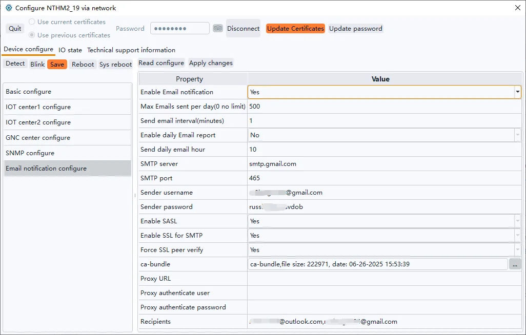
Taking Gmail's basic authentication SMTP as an example, this method will still be available until early 2026.
Connect to the device using the network configuration tool and click Email notification configure. Enable email notifications, enter the smtp.gmail.com on the SMTP server, port 465, enter the email name for the sending user name, enter the SMTP App password obtained above for the sending password, enable SASL, enable SMTP SSL, enable Force SSL peer verify, and the ca-bundle is a root certificate bundle provided by your trusted organization, here using the Mozilla CA certificate store. Finally, fill in the recipient email address, which is separated by a comma. For more information about each configuration item, refer to Email notification settings.
After the settings are completed, click Apply Changes -> Save -> Reboot to take effect.
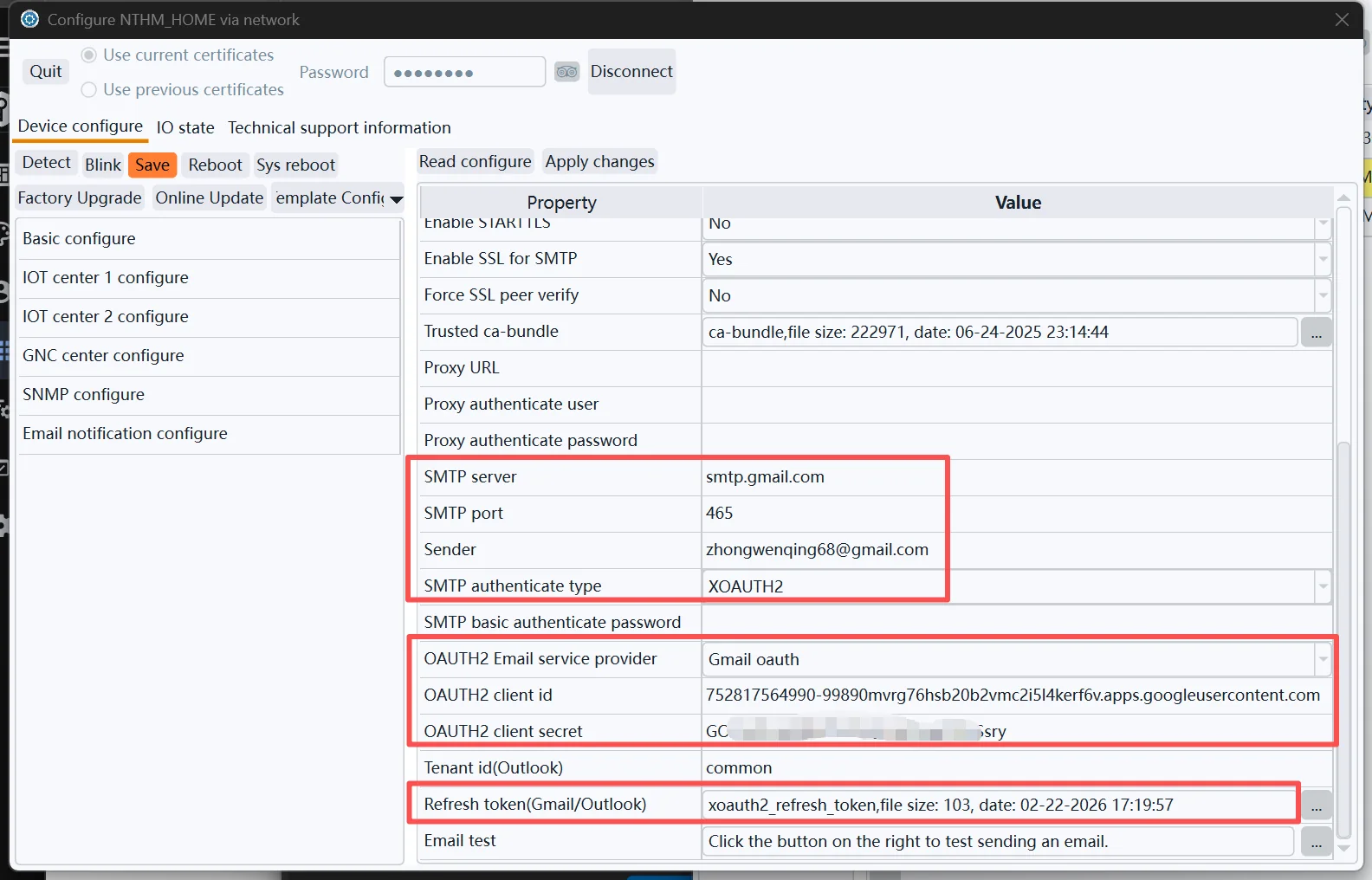
Gmail Sending Settings via OAuth2
Following the steps in Chapter 2, obtain the Client ID, Client secret, and Refresh Token file, and then configure them in the Email settings, similar to the screenshot below.
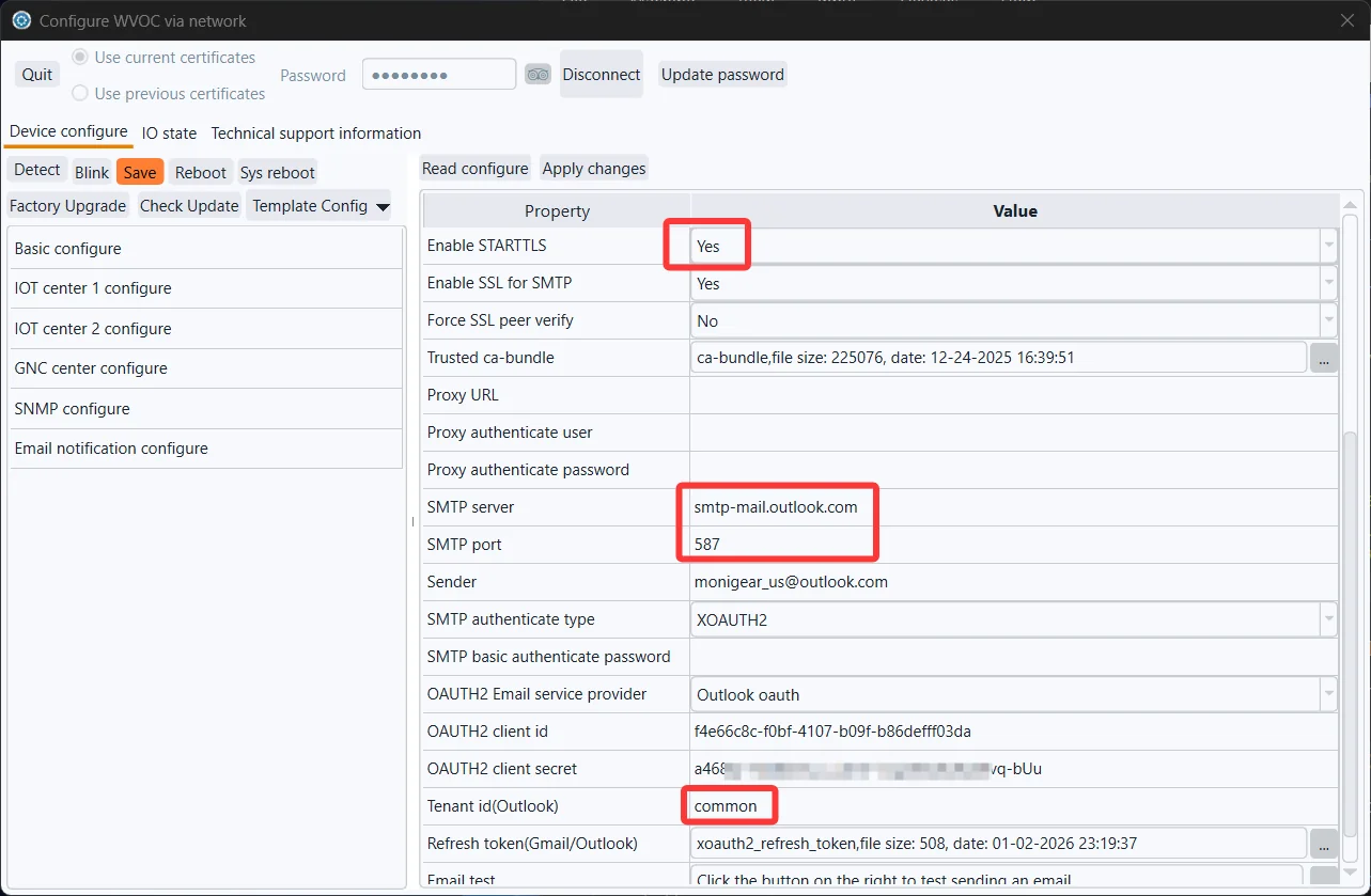
Outlook Sending Settings via OAuth2
Firmware versions released after January 2026 will support sending emails via Outlook. If your firmware version is older, you will need to upgrade before you can use Outlook to send emails. Refer to the screenshots below for the main configuration details. STARTTLS must be enabled in Outlook settings.
Send a test email
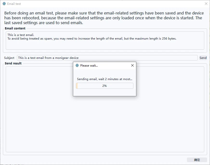
The process of sending an email involves multiple links (whether the device configuration is correct, whether the network is unblocked, whether the mail server is available, etc.), and any error in any link may lead to the failure of email delivery. Send a test email to display detailed debugging information when the email fails, troubleshoot the cause of the failure, and correct the configuration.

You can modify the content and title of the test email, and then click send to wait for the email to be sent.
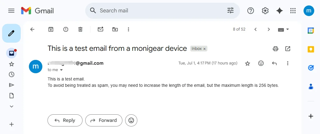
If the configuration is correct, a Success message will be displayed after the message is sent, as shown in the following figure:

Check the test email you received in your mailbox:
If the email is sent successfully, but you cannot receive the email, see Spam handling.
Example of sending failure:
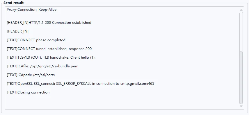
If you encounter any problems, you can send a screenshot of the configuration and the failure debugging information to our technical support technicians for help.
Statistics and information debugging information
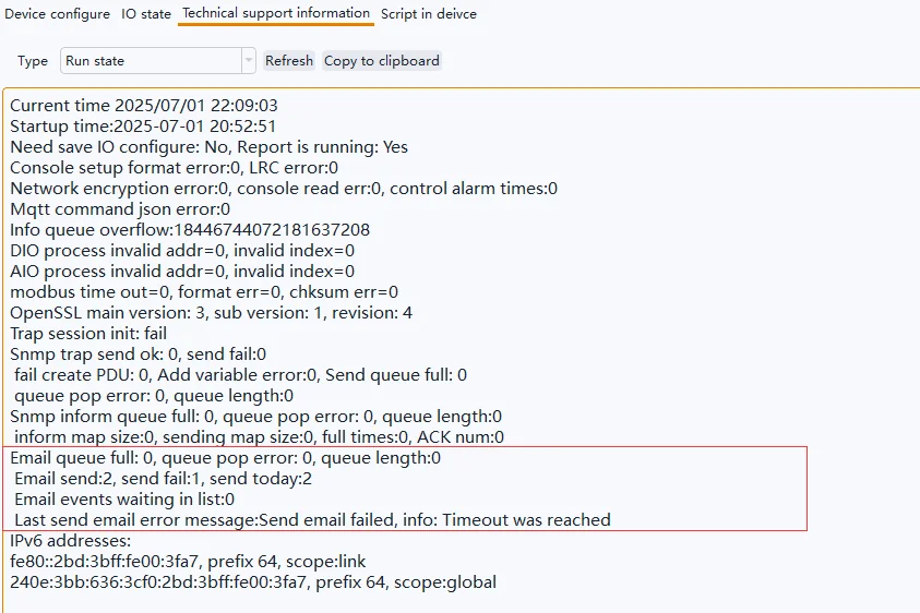
On the Technical support information page of the network configuration tool, select Run state and click Refresh to view the device running status and statistics. View the statistics of sent emails, in which email send is the number of emails that have been successfully sent, send fail has been sent failures, and send today is the number of times that have been successfully sent.
On the Technical support information page of the network configuration tool, select Run state and click Refresh to view the device running status and statistics. View email-related statistics.
Email send is the number of successful sents, send fail is the number of failed sends, and send today is the number of successful sends. Last send email error message is the reason for the most recent failed email.
If the email is sent successfully (the number of email sends increases) but the email cannot be received, see Spam handling.
Alarm settings for supervisory points(SP)
When an alarm event is triggered when the supervisory point of the device changes to the alarm threshold, the device sends an alarm email to the user. Each supervisory point of the Monigear device can set alarms separately, support delayed alarms, and provide up to 3 levels of alarms, usually level 3 is an emergency alarm, level 2 is an important alarm, and level 1 is a normal alarm. For a basic introduction to supervisory points, please refer to Appendix A
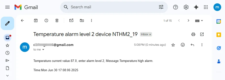
Example of a temperature alarm email:
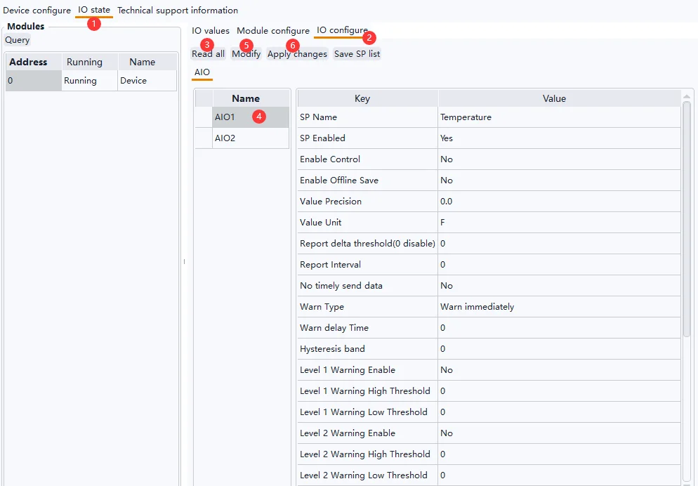
Use the network configuration tool, connect to the device, click IO state-> IO configure, click Read all, select a supervisory point, click Modify, modify the supervisory point configuration in the pop-up window, and then select other supervisory points to continue the configuration (see below for the alarm configuration description of each type of supervisory point), and after the configuration is complete, click Apply changes to apply the modification. For details about the configuration items of the monitoring points, see Appendix B.
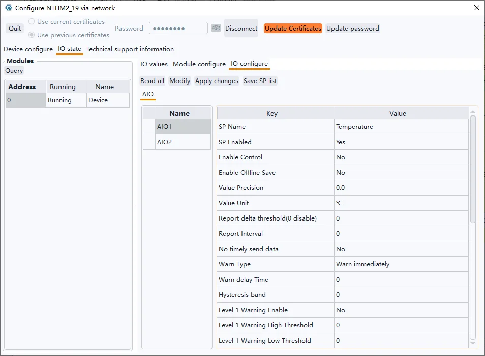
AIO alarm settings
Alarm threshold
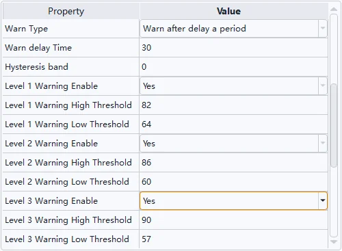
You can enable 1, 2, and 3 alarms, and set the upper and lower thresholds for each level.
① Example of temperature alarm setting (Fahrenheit):
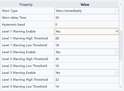
② Example of temperature alarm setting (Centigrade):
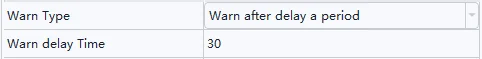
Delay alarm
As shown in the following figure, an alarm is triggered only after the temperature reaches the alarm threshold and is maintained for 30 seconds.
Hysteresis band
① Fahrenheit example:
When the temperature value rises to 82F, a Level 1 alarm will be triggered, and when the temperature value collected by the sensor fluctuates around 82F, it will cause frequent alarms to be triggered and the alarm will be extinguished, and the hysteresis band shown in the following figure will only be extinguished when the temperature drops below 80F.

② Centigrade example:
When the temperature value rises to 28℃, a Level 1 alarm will be triggered, and when the temperature value collected by the sensor fluctuates around 28℃, it will cause frequent alarms and alarm cancellations, and the hysteresis band shown in the following figure will only be extinguished when the temperature drops below 27℃.

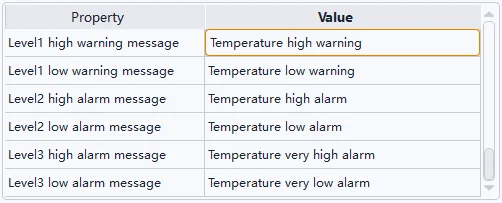
Alarm message
You can set the upper and lower limits of the 1/2/3 alarm level respectively, and describe the specific content of the alarm, the actions that need to be performed, and the installation location. To avoid mail delivery failures, do not use special characters.
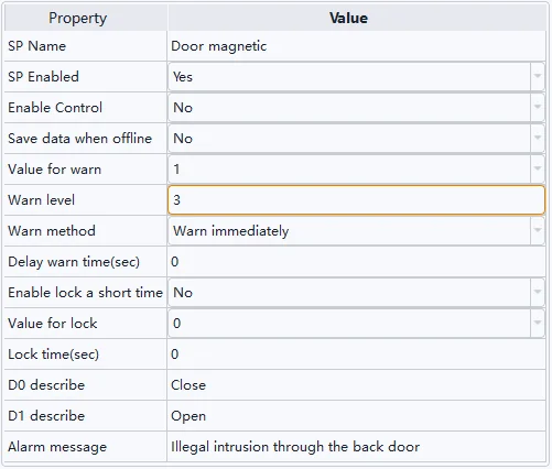
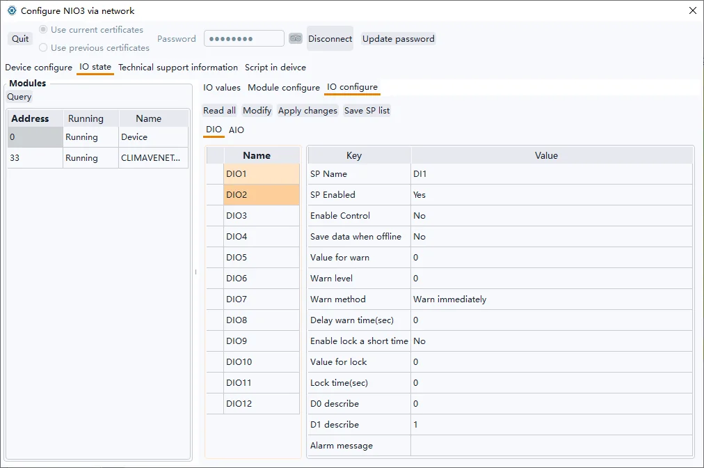
DIO alarm settings
As shown in the figure below, the DIO supervisory point corresponding to the door magnetic switch sensor is connected, and when the value is 1, it means that the door is open, triggering a level 3 alarm.
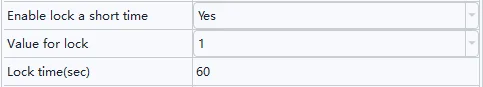
State locked
For security supervisory points, such as when using infrared probes for illegal intrusion detection, the sensor status may be switched frequently, and the status lock may be set to avoid frequent alarms and alarm canceling by the device. As shown in the figure below, after the sensor status value changes to 1, the status value of the device remains 1 for 60 seconds, regardless of how the sensor signal changes.
Delay alarms and alarm messages are set up in the same way as AIO.
Email notification settings
Maximum number of sends per day
Sending too many emails in a single day may result in the sending email account being banned by the service provider. Limiting the maximum number of devices sent per day is necessary, especially if multiple Monigear devices are configured to use the same mailbox to send alert emails.

Note that the maximum number of sends on the device is a weak limit, and the number of sends on the day will be recalculated after the device is restarted hot/cold. In addition, if an email fails to be sent, the number of sent items is not counted.
Send email Interval (Send email mode description)
Sending too quickly in a short period of time may also result in the sending email account being banned by the service provider. The interval between sending emails in two consecutive e-mails can be set at least 1 minute and up to 20 minutes.

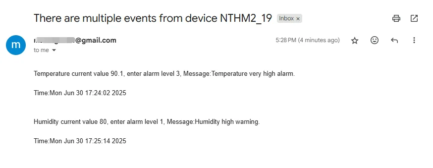
Monigear devices use a cached queue mode to send messages in order to minimize the number of times they are sent. After the previous email is successfully sent, a new (multiple) alarm event is generated during the waiting period for the sending interval, the event content will be cached, and when the interval time expires, all the cached content to be sent will be merged into one email for sending.
For example, you may receive an email with multiple alarm event information, as shown in the following image
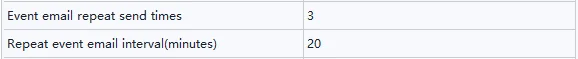
Repeat alarm
When an alarm is triggered at a supervisory point and the alarm state is entered, an alarm message will be sent once, and after that, if the alarm state is maintained and the alarm is not extinguished, the alarm message will be sent repeatedly, and the alarm message will be sent three times by default with an interval of 20 minutes. If the number of repetitions is set to 0, no repeated alarms will be sent, and the interval can be set to default 20 minutes, you can change it to 60 minutes for example.
Examples of repeat message:
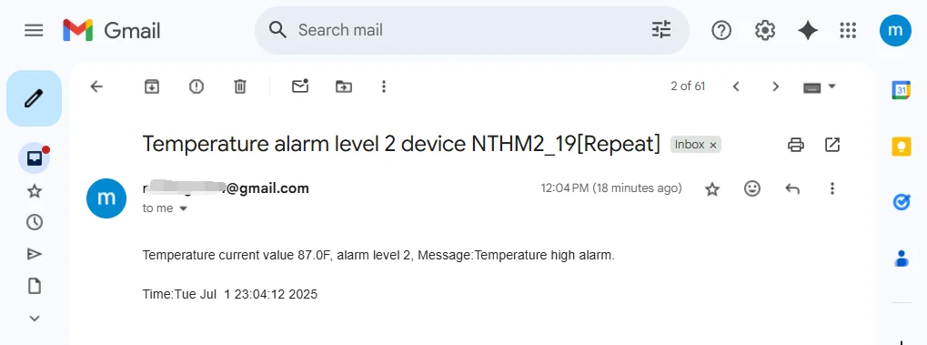
Tip: If the alarm description contains the current value and enter alarm level 1/2/3, it indicates that the alarm state is triggered, and only the current value contains the repeated alarm information.
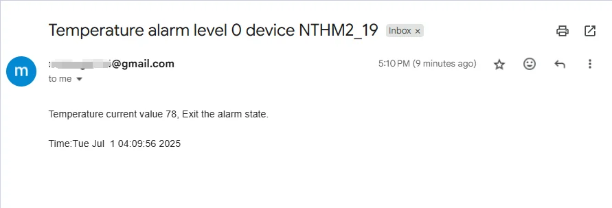
Exit the alarm notification
When the supervisory point exits the alarm state and returns to normal, an exit alarm message is sent.
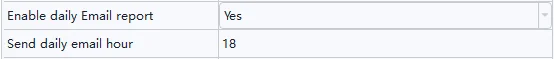
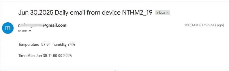
Sent at a timed daily time
Sometimes it is normal for a long time without any alarm events, so it is uncertain whether the device and email functions are normal. Therefore, we set up a function to send an email at a fixed time every day to let you know that the device is working normally.
Using a 24-hour clock, the hours can be set from 0 to 23.
Examples of timing messages:
When using the scheduled sending function, check the time zone of your region and modify it in the basic settings:

Recipient of the message
Multiple email addresses are separated by commas, and the maximum length of the string is 255. Each time a message is sent to multiple mailboxes, the corresponding number of times is accumulated.

Send it to yourself
It is allowed to use only one email account, both as a sender and as a receiver.
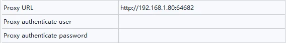
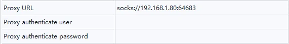
Use proxy
Example of an HTTP proxy:
Example of an SOCKS proxy:
SMTP non-encrypted port
If you use an SMTP non-encrypted port (the default port number is 25), you do not need to enable SSL and certificate verification.
Spam handling
Test emails or alarm emails sent by the device may be judged to be spam, and the recipient may not receive email notifications as scheduled. For example, in the following two cases, you can add the email address used to send alarm information to the whitelist in the recipient's mailbox settings.
Alert emails may be filtered as spam by the receiver and need to be viewed in the receiver's spam email.
The alert email may be judged as spam by the service provider where the recipient's email address is located and you cannot receive the alarm email.
Appendix A- Data Types of acquisition
The Monigear device represents the status data collected by the front-end sensor in the form of a supervisory point (SP), which is divided into four basic types: digital input/output(DIO), analog input/output(AIO), enumeration ENUM and string STRING.
| SP Type | Digital DIO | Analogue AIO | enumeration ENUM | STRING |
|---|---|---|---|---|
| Data type | Bool(0/1) | Float | Int | String |
| Example | Smoke sensorMotion detector | Temperaturevoltage | UPS、Generator status | IC card number |
Monigear devices have certain storage and computing capabilities, and can process the collected raw data on the device side and then report it to the server side, such as converting from raw values to displayed values, triggering alarms based on preset thresholds, executing linkage actions, etc. The following further explains the collected data values and alarm related contents.
Original value and displayed value
The raw value of the Monigear device data represents the data directly obtained from the sensor. When users read the device data through the standard communication protocol, they usually only care about the raw value. In some cases, the raw value is not easy to understand (for example, the two example DIOs in the following text have raw values of 1, one for water leak alarm and the other for normal), and it is necessary to combine the sensor information to get a readable display value corresponding to the monitored entity for the user.
Monigear devices provide corresponding conversion configurations for different types of monitoring points for users to modify (or refer to). Some communication protocols (such as SNMP GET) can directly read the conversion results. The following is an example of the conversion of original values and displayed values of each type. For a detailed description of monitoring point attributes, refer to the appendix B.
① dioValue和dioDetail
| dioValue | D0 descr | D1 descr | dioDetail |
|---|---|---|---|
| 1 | Normal | Leak alarm | Water leak |
| dioValue | D0 descr | D1 descr | dioDetail |
|---|---|---|---|
| 1 | Smoke alarm | Normal | Normal |
② aioValue和aioDetail
| Original | Precision | Unit | Display |
|---|---|---|---|
| 237.5146 | 0.0 | V | 237.5V |
③ enumValue和enumDetail
| Original | Enum string | Display |
|---|---|---|
| 1 | 0, No output1, Main power supply2, Battery supply…… | Main power supply |
④ strValue
Strings do not need to distinguish between raw and displayed values.
SP Alarm
Each supervisory point of the Monigear device can set an alarm individually, support delayed alarm, and provide up to 3 levels of alarms, usually level 3 is an emergency alarm, level 2 is an important alarm, and level 1 is a normal alarm. For the settings of various types of alarms, refer to the appendix B.
After the alarm is triggered, some communication protocols (such as SNMP GET, MQTT) can directly read the current alarm level. In addition, you can choose to send an email after the alarm, execute linkage actions (such as MN-NIO, control relay actions), etc.
Appendix B-Supervisory Point Configuration
DIO(Digital Input Output) Digital input and output configuration: including whether the channel is enabled, the value for alarm, the alarm level, whether it is a security monitoring point, delayed alarm time, etc.
| DIO Property | Value | Description |
|---|---|---|
| SP Name | The description of the DIO SP | |
| SP Enabled | Yes | This SP is enabled and the data will be reported to the center when conditions are met. |
| No | This SP is not enabled and will not be reported to the center. | |
| Enable Control | Yes | Digital output like relay that can be control |
| No | Digital input that cannot be controlled should be No | |
| Save data when offline | Yes | Keep the history data |
| No | Don’t keep the history data | |
| Value for warn | 0 | Digital value 0 is value for alarm |
| 1 | Digital value 1 is value for alarm | |
| Warn level | This item can only be 0, 1, 2, or 3 (0 means the alarm is not enabled) | |
| Warn method | Warn immediately | When the digital value is the same as the alarm value, an alarm is generated immediately. |
| Warn after delay a period | The digital value is the same as the alarm value and keep for a period of time then the alarm is generated. | |
| Delay warn time | Use with the previous item | |
| Enable lock a short time | Used for security SPs. Frequently changing digital signals will cause frequent alarms. Enabling this function can solve the problem of frequent alarms. | |
| Value for lock | When a state is locked for a period of time, if the digital input value changes to the locked value, the SP value will remain locked during the locked time, regardless of whether the value of the actual SP value changes during this period. | |
| Lock time | When the lock function is enabled, the SP remains unchanged for a certain period of time. | |
| D0 describe | A status description that is represented when the sensor signal value is 0 | |
| D1 describe | A status description that is represented when the sensor signal value is 1 | |
| Alarm message | Additional information when an alarm is triggered |
AIO(Analog Input Output) Analog input and output configuration: including whether the channel is enabled, precision, unit, upper and lower limits of effective value, alarm level, delayed alarm time, etc.
| AIO Properies | Value | Description |
|---|---|---|
| SP Name | Functional description of analog monitoring points | |
| SP Enabled | Yes | This SP is enabled and the data will be reported to the center when conditions are met. |
| No | This SP is not enabled and will not be reported to the center. | |
| Enable Control | Yes | For an analogue output |
| No | For an analogue input | |
| Enable Offline save | Yes | Save the history data |
| No | Don’t save history data | |
| Value Precision | The display precision of the SP value, for example, if it is set to 0.0, one decimal place will be retained | |
| Value Unit | The unit of the monitoring value, such as meter, ℃, etc. | |
| Send Var Condition | If the deviation between the monitored value and the last reported value is greater than this value, the monitored data will be immediately reported to the data center. | |
| Report interval | The frequency at which the SP is reported to the data center. If it is 0, the default system reporting interval is used (in the basic configuration category, the default is 20 minutes) | |
| No timely send data | Yes | When the device reports all monitoring data regularly, the value of this monitoring point is not reported. |
| No | When the device reports all SP data regularly, it reports the value of the monitoring point | |
| Warn Type | Warn immediately | When the monitoring value is higher than the upper alarm limit or lower than the lower alarm limit, an alarm is immediately issued |
| Warn after delay a period | An alarm is generated only when the monitoring value is higher than the upper alarm limit or lower than the lower alarm limit and keep for a period of time. | |
| Warn delay time | Use with the previous item | |
| Hysteresis band | The difference between the monitoring value and the alarm threshold must be greater than the hysteresis band value to meet the alarm cancellation condition, which can avoid frequent alarm triggering near the critical point. For example, if the alarm is set to be greater than 36°, if this value is set to 0.5, the alarm state will be cancelled only when the value is less than 35.5. | |
| Level 1/2/3 Warning Eanble | When the monitoring value meets the conditions, an alarm of the corresponding level will be generated | |
| Level 1/2/3 warning high threshold | When the monitoring value is higher than the alarm upper threshold, an alarm of the corresponding level will be generated | |
| Level 1/2/3 waring low threshold | When the monitoring value is lower than the alarm lower threshold, an alarm of the corresponding level will be generated | |
| Minimum value | The lower limit of the external transmitter range | |
| Maximum value | The upper limit of the external transmitter range | |
| Level1 high warning message | Additional information when a Level 1 high-limit alarm is triggered | |
| Level1 low warning message | Additional information when a Level 1 low-limit alarm is triggered | |
| Level2 high alarm message | Additional information when a Level 2 high-limit alarm is triggered | |
| Level2 low alarm message | Additional information when a Level 2 low-limit alarm is triggered | |
| Level3 high alarm message | Additional information when a Level 3 high-limit alarm is triggered | |
| Level3 low alarm message | Additional information when a Level 3 low-limit alarm is triggered |