Monigear Modbus TCP User Guide
Monigear Device - Modbus TCP Communication Protocol
1. Protocol Introduction
Modbus TCP uses Ethernet TCP/IP to transmit Modbus messages between sites. TCP/IP network provides data segmentation, confirmation, retransmission, addressing, routing, and other functions, ensuring that Modbus messages are correctly routed, reliably, and orderly transmitted between Ethernet devices, achieving efficient and reliable data exchange.
2. Client-Server Communication
Modbus TCP adopts a master-slave response method. The upper computer acts as the client (master) to send requests over the network, and the server (slave) processes the requests and sends back responses. The device acts as the server, actively listening to TCP port 502, waiting for client connection requests. After the connection is successfully established, it responds to data communication requests that comply with the Modbus TCP protocol.
3. Protocol Format
Modbus TCP data frame consists of the message header MBAP and the frame structure PDU. The MBAP header is 7 bytes long, composed as follows:
| Transaction Identifier | Protocol Identifier | Length | Unit Identifier |
|---|---|---|---|
| 2 bytes | 2 bytes | 2 bytes | 1 byte |
3.1 Description of each part of the MBAP:
| Content | Description |
|---|---|
| Transaction ID | Sequence number of the message, generally incremented by 1 for each communication, used to distinguish different packet. |
| Protocol ID | 00 00 indicates Modbus TCP |
| Length | the length of the following data, in bytes |
| Unit ID | Identifies the target device or unit within the Modbus network, can be understood as the device address |
The PDU frame structure consists of a function code and a data field. The function code is 1 byte long, and the length and content of the data field depend on the specific function. The function codes supported by the device are as follows:
| Function Code | Function | Description |
|---|---|---|
| 0x01 | Read Coils | Read one or more digital input/output (DIO) data |
| 0x03 | Read Holding Registers | Read one or more analog input/output (AIO) data |
| 0x05 | Write Single Coil | Write/control a single digital output (DIO) |
| 0x06 | Write Single Holding Register | Write/control a single analog output (AIO) |
3.2 Example: Reading Digital input
Request frame information: Read device address 1, coil starting address 0000, and read 8 coils.
| Transaction Identifier | Protocol Identifier | Length | Unit ID | Function Code | Coil Starting Address | Number of Coils | |||||
|---|---|---|---|---|---|---|---|---|---|---|---|
| 0x00 | 0x01 | 0x00 | 0x00 | 0x00 | 0x06 | 0x00 | 0x01 | 0x00 | 0x00 | 0x00 | 0x08 |
Response frame information:
| Transaction Identifier | Protocol Identifier | Length | Unit ID | Function Code | Number of Data Bytes | Data Content | |||
|---|---|---|---|---|---|---|---|---|---|
| 0x00 | 0x01 | 0x00 | 0x00 | 0x00 | 0x06 | 0x00 | 0x01 | 0x01 | 0xFF |
3.3 Example: Reading Analog Inputs
Request frame information: Read device address 0, register starting address 0002, and read 2 registers.
| Transaction Identifier | Protocol Identifier | Length | Unit ID | Function Code | Register Starting Address | Number of Registers | |||||
|---|---|---|---|---|---|---|---|---|---|---|---|
| 0x00 | 0x02 | 0x00 | 0x00 | 0x00 | 0x06 | 0x00 | 0x03 | 0x00 | 0x02 | 0x00 | 0x02 |
Response frame information:
| Transaction Identifier | Protocol Identifier | Length | Unit ID | Function Code | Number of Data Bytes | Data Content (HEX) | ||||||
|---|---|---|---|---|---|---|---|---|---|---|---|---|
| 0x00 | 0x02 | 0x00 | 0x00 | 0x00 | 0x07 | 0x00 | 0x03 | 0x04 | 59 | 17 | 42 | 43 |
3.4 Communication Errors
Typically, the master (computer) sends request data to the slave (device), and the slave responds and processes the request. However, communication errors may occur in the following situations:
TCP/IP network anomalies, detected by the master program as query timeout or network interruption.
The slave receives the request data without communication errors but cannot process it (e.g., reading a nonexistent register address) and reports the error to the master.
When the slave reports an error, the function code and data field differ from a normal response.
Function Code:
For normal responses, the slave's response function code is the same as the master's request function code. All function codes have an MSB of 0 (value less than 80H).
For abnormal responses, the slave sets the MSB of the function code to 1, making the value greater than 80H, higher than normal response values. The master application identifies abnormal response events by recognizing these values and checks the error code further.
Data Field:
For normal responses, the data field contains the data or statistics requested.
For abnormal responses, the data field contains an exception code explaining the condition and reason for the abnormal response.
Error Codes and Meanings
| Code | Name | Meaning |
|---|---|---|
| 0x01 | Illegal Function | The received function code does not exist in the slave's program. |
| 0x02 | Illegal Data Address | The requested data address is not allowed by the slave; e.g., incorrect starting address for coils or registers, query count exceeds valid range. |
Example: Abnormal Response
Request frame information: Read device address 0, register starting address 0123, and read 2 registers.
| Transaction Identifier | Protocol Identifier | Length | Unit Id | Function Code | Register Starting Address | Number of Registers | |||||
|---|---|---|---|---|---|---|---|---|---|---|---|
| 0x00 | 0x03 | 0x00 | 0x00 | 0 | 0x06 | 0x00 | 0x03 | 0x01 | 0x23 | 0x00 | 0x02 |
Response frame information: Due to incorrect register starting address, the response indicates an illegal data address.
| Transaction Identifier | Protocol Identifier | Length | Unit Id | Function Code | Data Content | |||
|---|---|---|---|---|---|---|---|---|
| 0x00 | 0x03 | 0x00 | 0x00 | 0x00 | 0x07 | 0x00 | 0x83 | 0x02 |
Enabling Modbus TCP Function on the Device
Use the network device configuration tool to connect to the device, then enable the Modbus TCP function in the basic settings.
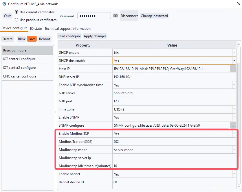
Modbus TCP Function Configuration Items
| Configuration Item | Description |
|---|---|
| Enable Modbus TCP | Enable this function, because the modbus tcp function is not a safe way for communication in the internet, so it was disabled by default. |
| Modbus tcp port | Default 502 |
| Modbus tcp mode | Server mode/Client modeServer mode is default. Some software developers want the device to actively connect to a certain port of the server, and only after the connection is connected will the software side initiate the query command of the modbus protocol, so the corresponding client mode has been developed. |
| Modbus tcp server ip | Center IP to connect to in client mode |
| Modbus tcp idle timeout | Disconnect and reconnect if idle for a long time (unit is minutes) |
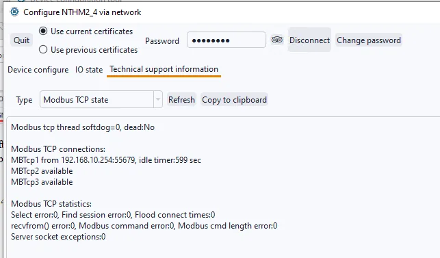
The device's Modbus TCP function supports up to 3 clients connected to the device's TCP 502 port in server mode. Check the status statistics of this function in the technical support information.
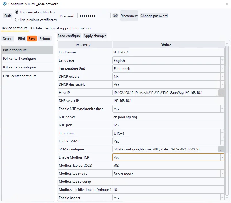
Test Example
Using the network temperature and humidity transmitter MN-NHTM as an example, enable the Modbus TCP function and use the testing tool mbpoll to read real-time temperature and humidity data.
Refer to the following diagram for device IP and function settings, for example:
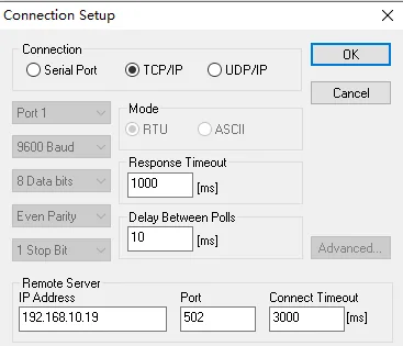
Viewing Current Temperature and Humidity
Open the mbpoll testing tool, select Connection -> Connect (shortcut key F3) from the menu bar, choose TCP/IP in the connection settings page, and enter the device's IP address and default port number 502.
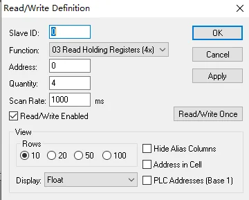
After successfully connecting to the device using mbpoll, select Setup -> Read/Write Definition (shortcut key F8) from the menu bar. Set the Modbus TCP command's device address/SlaveID, function code, data address, quantity to read, and display method.
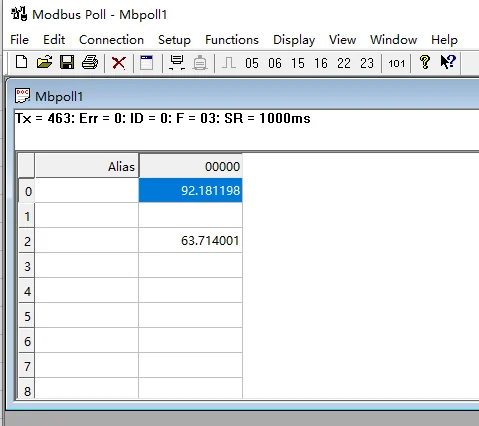
Viewing Real-Time Temperature and Humidity Values
Modbus Address Table
Common Modbus address table for devices.
In Modbus protocol, when function code 03 is used to read address 0, the corresponding register address described in the protocol is 40001. Therefore, if some software uses the standard protocol's 4xxxx format address representation, you should add 40001 to the address mapping table below to correspond to it.
Our WiFi series and PoE series use the same address table.
6.1 Network Temperature and Humidity Transmitter MN-NHTM/WTHM
Analog values (device address 0/255, function code 0x03)
| Address | Name | R/W | Data type | Unit | Remark |
|---|---|---|---|---|---|
| 0 | Temperature | R | Float | ℃/F | -30-85 ℃ |
| 2 | Hmidity | R | Float | % RH | 0-100 %RH |
6.2 Network series Gas transmitter
MN-NCO2 for monit CO2 concentration
Analog values (device address 0/255, function code 0x03)
| Address | Name | R/W | Data type | Unit | Remark |
|---|---|---|---|---|---|
| 0 | Gas Indicator (CO2 Concentration) | R | Float | ppm | 0-2000ppm |
MN-NCO2TH 3in1 indoor air quality monitor
Analog values (device address 0/255, function code 0x03)
| Address | Name | R/W | Data type | Unit | Remark |
|---|---|---|---|---|---|
| 0 | CO2 Concentration | R | Float | ppm | 0-2000ppm |
| 2 | Temperature | R | Float | ℃/F | -30-85 ℃ |
| 4 | Hmidity | R | Float | % RH | 0-100 %RH |
MN-NVOC/WVOC 4in1 indoor air quality monitor
Analog values (device address 0/255, function code 0x03)
| Address | Name | R/W | Data type | Unit | Remark |
|---|---|---|---|---|---|
| 0 | CO2 Concentration | R | Float | ppm | 0-2000ppm |
| 2 | Temperature | R | Float | ℃/F | -30-85 ℃ |
| 4 | Hmidity | R | Float | % RH | 0-100 %RH |
| 6 | TVOC | R | Float | ppb | 0-9999ppb |
6.3 Multifunction Input/Output Module MN-NIO
Digital values (device address 0, function codes 0x01/0x05)
| Address | Name | R/W | Data type | Description | 备注 |
|---|---|---|---|---|---|
| 0 | DI1 | R | bit | 0: closed,1:open | Digital input1 |
| 1 | DI2 | R | bit | 0: closed,1:open | Digital input2 |
| 2 | DI3 | R | bit | 0: closed,1:open | Digital input3 |
| 3 | DI4 | R | bit | 0: closed,1:open | Digital input4 |
| 4 | DI5 | R | bit | 0: closed,1:open | Digital input5 |
| 5 | DI6 | R | bit | 0: closed,1:open | Digital input6 |
| 6 | DI7 | R | bit | 0: closed,1:open | Digital input7 |
| 7 | DI8 | R | bit | 0: closed,1:open | Digital input8 |
| 8 | DO9 | RW | bit | 0: open,1:closed | Relay1 |
| 9 | DO10 | RW | bit | 0: open,1:closed | Relay2 |
| 10 | DO11 | RW | bit | 0: open,1:closed | Relay3 |
| 11 | DO12 | RW | bit | 0: open,1:closed | Relay4 |
Note: The general used digital input interface corresponds to the dry contact sensor, and the actual name and 0/1 value description of each channel are defined depending on the sensor type. For example, the smoke alarm connected to DI1 is actually called smoke detector status, 0: normal 1: alarm.
Analog values (device address 0, function code 0x03)
| Address | Name | R/W | Data type | Unit | Remark |
|---|---|---|---|---|---|
| 0 | AI1 | R | Float | \ | Analog input1 |
| 2 | AI2 | R | Float | \ | Analog input2 |
| 4 | AI3 | R | Float | \ | Analog input3 |
| 6 | AI4 | R | Float | \ | Analog input4 |
| 8 | AI5 | R | Float | \ | Analog input5 |
| 10 | AI6 | R | Float | \ | Analog input6 |
| 12 | AI7 | R | Float | \ | Analog input7 |
| 14 | AI8 | R | Float | \ | Analog input8 |
Note: The general used analogue input interface corresponds to industrial standard 4-20mA sensors, and the actual name and unit of each channel depends on the sensor type. For example, AI1 is connected to a 4-20mA water level transmitter, which is actually called water level. In addition, the upper and lower limits of analog quantities are further set according to the range of the sensor.
MODBUS address table for function code 4
In the address table of function code 3 above, when reading each analog value, two consecutive registers (2 bytes each register) are read to represent a 4-bytes float data. This representation style is inherited from our monitoring host. Because it is a general interface that may connect to various type sensors, and the range of sensor values cannot be determined in advance, using the float data to represent a wide range of sensor data can be applied to various industrial SCADA applications.
However, some customers have reported that this data parsing method is complicated when connecting to their software. Therefore, for our temperature, humidity and gas series sensors, since the data range is known, we have made a firmware upgrade to provide data response based on function code 4, where each register represents the value of an analog supervisory point.
Note: Function code 4 is only supported on firmware versions with a date after 2026/01/17. Older devices can gain this feature through upgrades under our guidance, please contact our technical support before upgrade.
In MODBUS protocol, when function code 04 is used to read address 0, the corresponding register address described in the protocol is 30001. Therefore, if some software uses the standard protocol's 3xxxx format address representation, you should add 30001 to the address mapping table below to correspond to it.
MN-NTHM/WTHM temperature and humidity transmitter,
Analog values (device address 0/255, function code 0x04)
| address | Name | R/W | Data type | Unit | Remark |
|---|---|---|---|---|---|
| 0 | Temperature | R | Int | 0.1℃ | -30-85 ℃ |
| 1 | Humidity | R | Int | % RH | 0-100 %RH |
MN-NCO2TH 3in1 indoor air quality monitor
Analog values (device address 0/255, function code 0x04)
| address | Name | R/W | Data type | Unit | Remark |
|---|---|---|---|---|---|
| 0 | CO2 concentration | R | int | ppm | 400-2000 ppm |
| 1 | Temperature | R | int | 0.1℃ | -30-85 ℃ |
| 2 | Humidity | R | int | % RH | 0-100 %RH |
MN-NVOC/MN-WVOC 4in1 indoor air quality monitor
Analog values (device address 0/255, function code 0x04)
| Address | Name | R/W | Data type | Unit | Remark |
|---|---|---|---|---|---|
| 0 | CO2 concentration | R | int | ppm | 400-2000 ppm |
| 1 | Temperature | R | int | 0.1℃ | -30-85 ℃ |
| 2 | Humidity | R | int | % RH | 0-100 %RH |
| 3 | TVOC | R | int | ppb | 0-9999ppb |